 立即咨询
立即咨询 联系我们
联系我们技术与研发
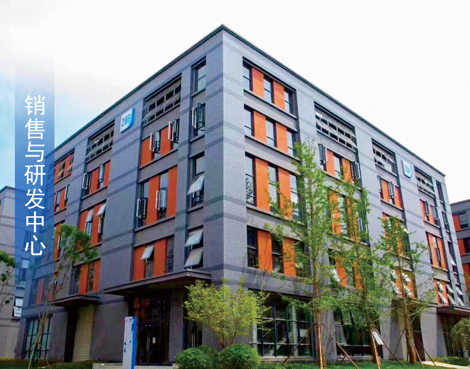
蒸发结晶行业经验近20年集团已深扎于蒸发结晶行业经验近20年,拥有高级工程师、工程师等各类专业技术人员近百人。设有5000+平方米销售与研发中心,与数名国外资深zj****和国内各行业高级工程师合作,并与多所知名大学与教授联合攻关课题,自建实验室、中试设备。 金龙配备的水质检测实验室,可对原料进行简单的化学分析、检测蒸发物料的蒸发结晶状态、沸点温升,物料原料及冷凝水的 PH、COD、粘度等物性特征,定制化方案满足客户个性化需求。
查看更多


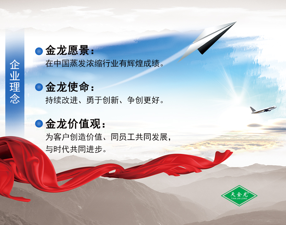
金龙蒸发,创绿⾊⼯程,为您提供专业的蒸发结晶系统解决方案!
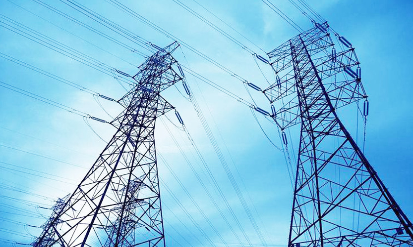
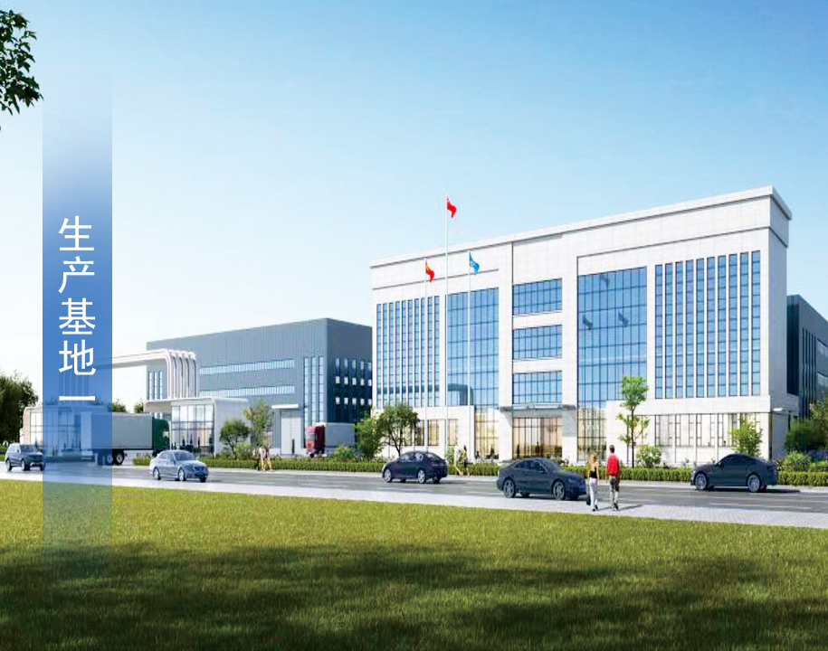
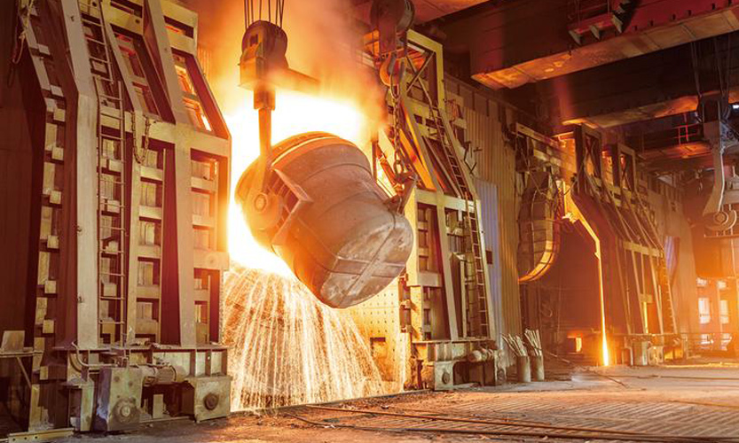
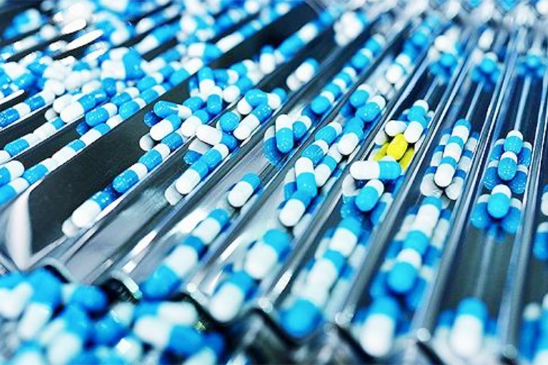
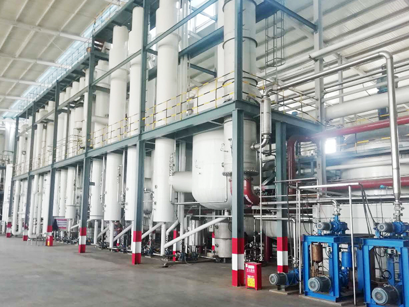
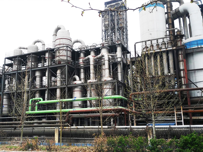
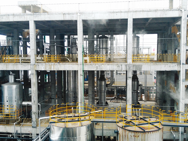
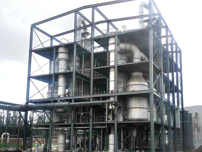
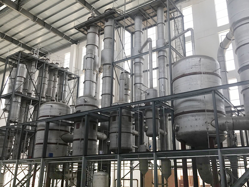
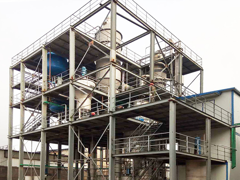
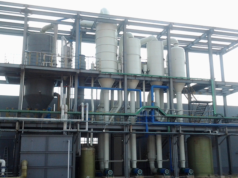
金龙机械集团-创立于1998年,公司专业生产各类蒸发、浓缩、结晶设备,提供蒸发、浓缩、结晶单元的整体工艺方案设计,成套设备生产、制造、安装、调试、培训交钥匙工程。集团总部和技术研发中心位于南京市江北新区,集团生产基地位于安徽的东大门-天长市,拥有现代化的制造基地及售后服务中心。产品主要应用于环保污水处理、高盐废水处理、生物发酵、新能源锂电、化工、制药、造纸、钢铁、电力、冶金、食品等领域......【查看更多】
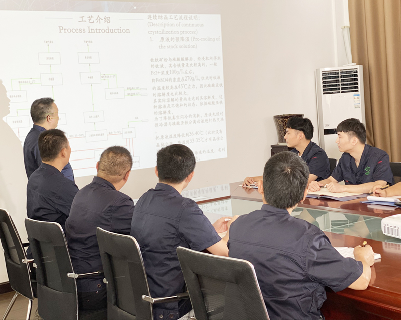
集团已深扎于蒸发结晶行业经验近20年,拥有高级工程师、工程师等各类专业技术人员近百人。设有5000+平方米销售与研发中心,与数名国外资深zj****和国内各行业高级工程师合作,并与多所知名大学与教授联合攻关课题,自建实验室、中试设备。 金龙配备的水质检测实验室,可对原料进行简单的化学分析、检测蒸发物料的蒸发结晶状态、沸点温升,物料原料及冷凝水的 PH、COD、粘度等物性特征,定制化方案满足客户个性化需求。
查看更多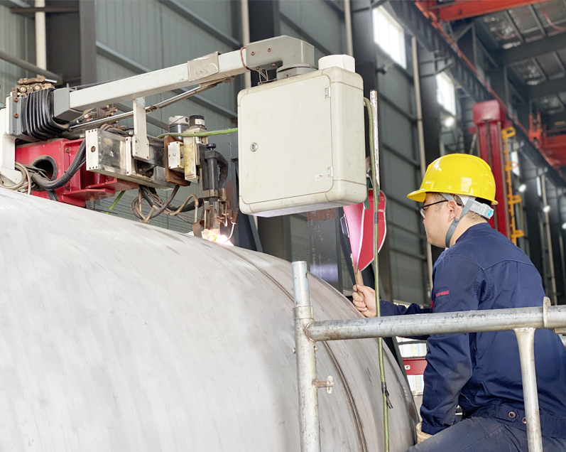
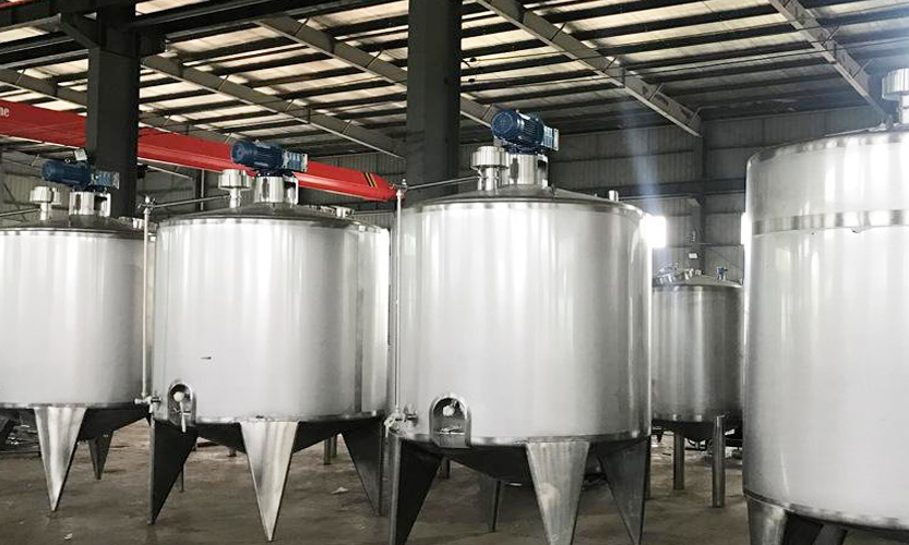
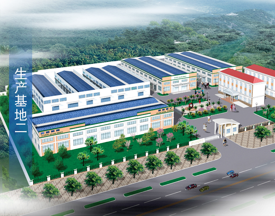
公司拥有60000+平方米生产基地、配置各种数控机床、等离子自动切割机、自动抛光机、立柱式等离子自动焊机、管板自动焊机等。 技术zj****直接参与生产,保证产品的稳定可靠和万无一失。
查看更多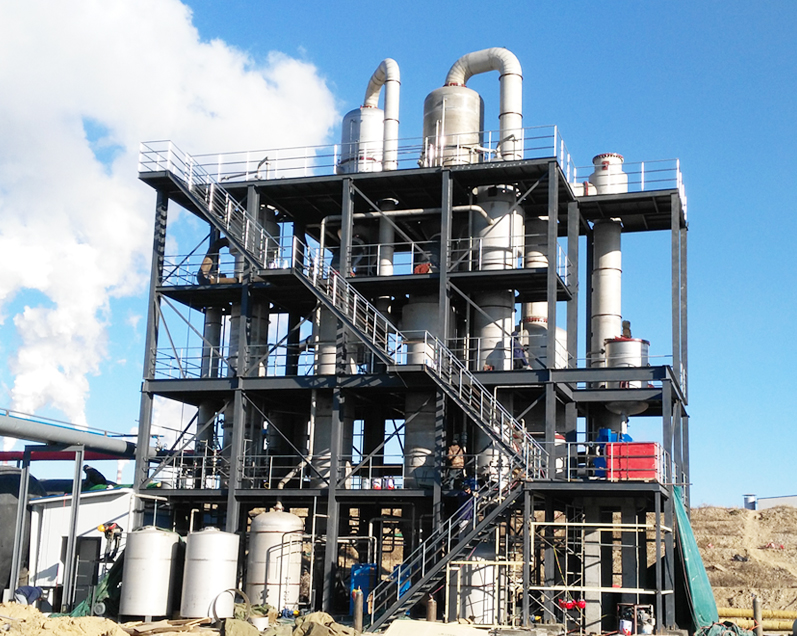
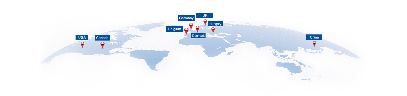
目前,湖南裕能、华友钴业、贵州雅友、龙蟒佰利联、中核钛白、中山化工集团、万山化工集团、彩客化学集团、中粮集团、石药集团、联邦制药、诸城兴贸、西王集团等国内知名集团公司均成为金龙机械集团的战略合作伙伴。集团拥有产品自营进出口权,产品远销欧美及东南亚等******和地区。
查看更多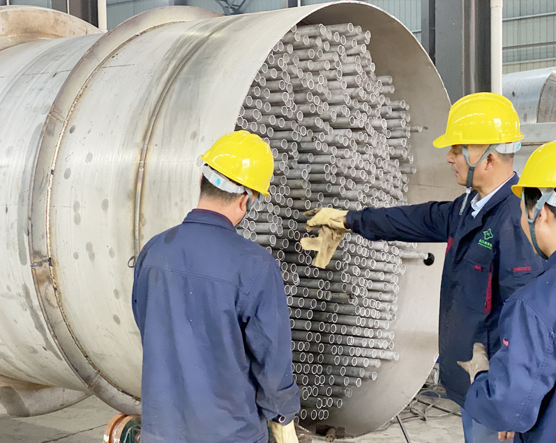
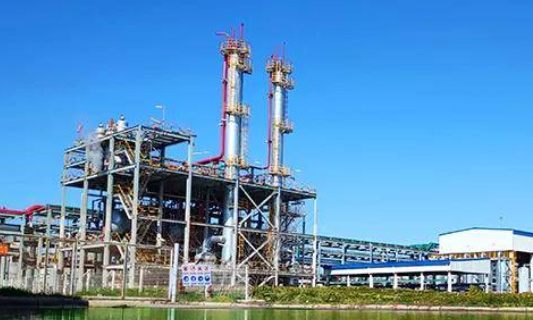
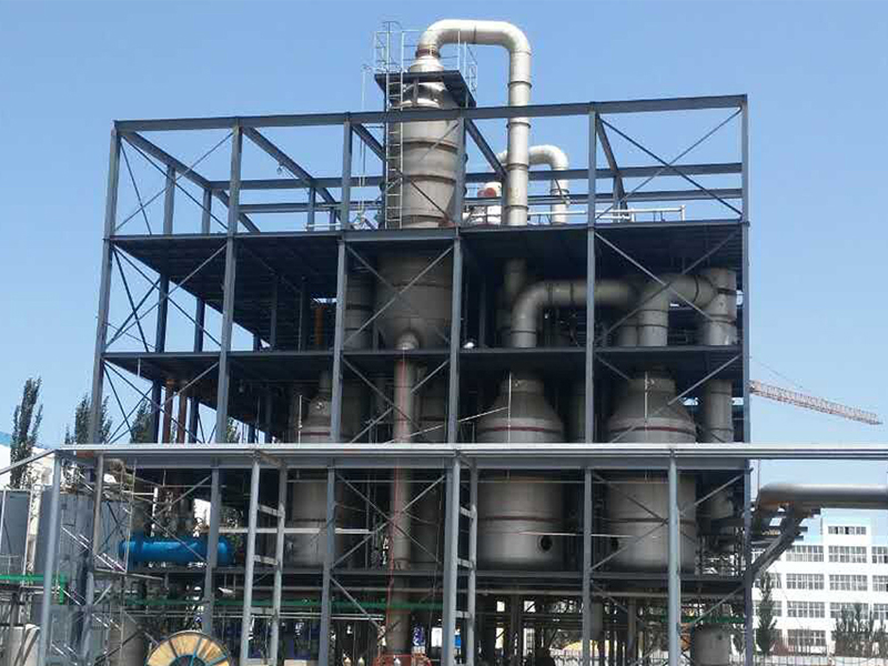
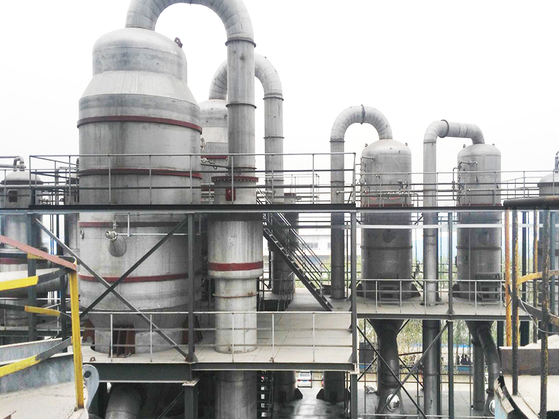
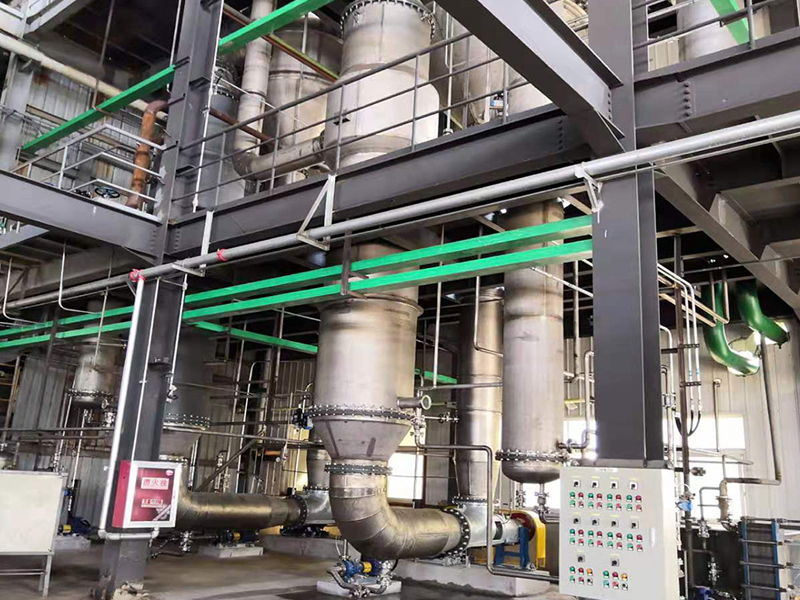
我公司蒸发浓缩系统,从控制方案设计、选型、编程到安装调试为客户提供交钥匙工程,已经完全实现系统的自动化控制。金龙运用xj****的三维设计软件,在设计阶段即可呈现工程实施冗成之后的全貌。
查看更多
节 能、先 进、稳 定
电话:0550-7305788 7033788
手机:13913986648(微信同号)
网址: www.fourstatesgasket.com
邮箱:ahjljx@jinlongzf.cn